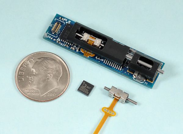
Integrated motion control module contains an SQL-RV-1.8 SQUIGGLE motor and an NSD-2101 smart driver ASIC .
Published by ECN magazine
May 2013
By David Henderson
Advances in piezo motor driver electronics include efficient full-bridge switching, integrated frequency generation and tracking, speed control and digital control. These combine to reduce system power by approximately 40% while maintaining output power (motor speed), maintaining optimal motor performance despite manufacturing variations and temperature changes, and producing smoother, quieter motion.
Piezoelectric ultrasonic motors (piezo motors) are a distinct class of rotary and linear actuators that require unique driving circuits to achieve practical, reliable, precise and efficient operation. A piezo motor uses the ultrasonic vibrations (greater than 20 kHz) of a “stator” structure that is frictionally coupled to a moving slide or rotating shaft. Piezo motors with operating frequencies from 40 to 700 kHz are commercially available.
The vibrations are generated using piezoelectric elements which are capacitors that change shape when charged and discharged. The vibration frequency corresponds to the resonant frequency of the structure and uses the mechanical Q (amplification) to multiply piezo element movements of 10 to 100 nanometers to motor movements of 1 to 10 micrometers. For most piezo motors, two orthogonal vibrations are generated that combine to produce Lissajous motions with a preferred direction that is changed by changing the drive frequency or phase.
Co-fired multi-layer piezoelectric elements are now available that operate efficiently at ultrasonic frequencies with the drive voltage supplied directly from a battery. This motor innovation eliminates the need for a DC-DC voltage boost to 40 or 200 volts, and enables small, efficient and smart drive circuits which are similar in size and cost to stepper and DC motor drive solutions. Two examples of piezo motor driver ICs are the NSD2101 from ams (figure 1) and the LT3572 from Linear Technologies.
Smart piezo motor driver ICs provide two-channel outputs, efficient full-bridge switching, integrated frequency generation and tracking, speed control and digital control.
Two-channel outputs
Two-channel outputs are used to drive independent piezo elements in the motor. The ideal drive waveforms are sinusoidal and excite only the fundamental motor frequencies without generating undesirable harmonic vibrations. Square waveforms are much more efficient to generate using solid-state switches and work very well for most piezo motor designs. The direction of the Lissajous vibration is determined by the phase shift between the drive signals. Typically + 90 degrees is one direction and -90 degrees is the opposite direction.
Full-bridge switching
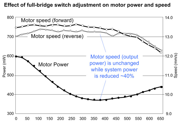
Efficient full-bridge switching into the capacitive piezo elements has the benefit of doubling the effective voltage from the battery and the corresponding vibration amplitudes. The “square” wave signals are actually trapezoidal due to the RON of the circuit as well as active current limiting. In general, the rise and fall time of the waveform should be less than 5 percent of the period. Current limits protect the piezo elements and the drive circuits and reduce the overall system power. Recent advances in the sequence and timing of the full-bridge switching has demonstrated an additional 40 percent input power reduction without reducing the piezo motor force and speed (figure 2).

Fig. 2: With full-bridge switching, system power is reduced approximately 40% while motor speed (output power) is unchanged
Integrated frequency generation and tracking
Peak system performance is realized when the drive signal frequency matches the resonant frequency of the motor within about 0.5 percent. However, the piezo motor resonant frequency will vary by more than 3 percent due to manufacturing tolerances and operating temperature. Smart driver ICs incorporate a method to generate, measure and lock on to the motor resonance during normal operation, thereby maintaining peak performance. One effective method is to periodically sweep the drive frequency and measure the current. The peak current frequency can be used to calculate the optimum drive frequency for a specific motor.
Hybrid speed control
Motor speed control is also a very desirable feature for piezo motor systems. Direct speed control enables smoother and quieter motion. In addition, for battery-powered systems, speed control maintains stable performance as the supply voltage changes.
Speed is proportional to the effective voltage delivered to the piezo elements. Two available methods of speed control are pulse-width modulation (PWM) and hybrid switching (Hybrid). PWM is similar to other motor controllers, where the duty cycle of each period of the driving waveforms is adjusted from 0 to 50 percent, which corresponds to zero to maximum velocity. In practice, piezo motors stop moving when the duty cycle is less than 20 percent. Hybrid speed control adjusts the ratio of full-bridge and half-bridge waveforms delivered to the piezo elements to adjust the effective voltage. Hybrid control is more efficient than PWM and adjusts the effective voltage from two times the supply voltage to one times the supply voltage. When PWM and hybrid speed control are used together, the maximum velocity adjustment range is achieved.
Small smart drivers key to integrated modules
The smart driver ICs are small, typically less than 2 x 2 mm, and easily co-located with the piezo motor to create miniature, integrated drive systems. The short connection minimizes EMI of the ultrasonic waveforms. The I/O to a smart IC is DC power from a battery and digital commands via an I2C port.
Motion control modules (figure 3) with integrated piezo motor and new smart drive IC, along with a Hall effect position sensor, processor, firmware and micromechanical assembly, not only optimize motor performance but also make system integration simple and fast.

Figure 3: Integrated motion control module contains an SQL-RV-1.8 SQUIGGLE motor (New Scale Technologies) and an NSD-2101 smart driver ASIC (ams).
Learn more about M3 Modules that implement these advanced control techniques with reduced-voltage SQUIGGLE motors and integrated controllers.


